 Deutsch
 English
Hole tolerances, production capabilities and technology data
Accurate machinery and clamping devices, precise tools, optimized cutting values, high-quality lubricants and not least - our skilled employees with long term expericence - guarantee first-class drilling results.
Generally applicable tolerances (not depending on the drill diameter)
|
ISO based standard tolerance: |
IT9 |
|
position tolerance (spot drilling): |
 Ø0.1 mm |
|
|
|
|
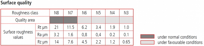
Surface roughness Ra: |
*1.6 bis 3.2 µm |
|
Surface roughness Rz: |
*15 bis 25 µm |
|
*The mentioned roughnesses are indicative values due to this the values for bore surface roughness of non-ferrous metals like titanium or aluminium can be less than Ra 1.0 µm. |
|
|
|
|
|
Max. drill depth when drilling from one side: |
2,000 mm (78 3/4 inches) |
|
Max. drill depth when drilling from both sides: |
4,000 mm (157 1/2 inches) |
|
|
|
|
Max. workpiece weight: |
5,500 Kg (12,000 lbs) |
Deep-hole bores starting at Ø 1 mm - drilling with single flute drills (gun drills)
|
Runout (drift of the tool): |
0.1 mm / 100 mm drill depth within a total drilling depth of 70 x bore diameter |
|
Bore diameter tolerance: |
0 / -0.3 mm up to bore diameter 18 mm equals IT8 (depending on the material) |
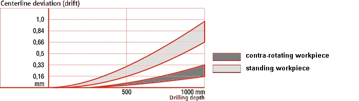
The ratio of drill tool drift to drill depth of 0.1 mm per 100 mm drill depth
is to be recognized as an empirical formula to calculate the approximate runout.
An more accurate illustration is shown within the following figure.
Usually deep hole drilling tools hardly have middle axis drift.
If drilling into cylindrical shaped workpieces the tool and workpiece are contra-rotating.
Due to this the tool drift is being halved (tinted area).
Diagrams concerning the centerline deviation, straightness, surface quality and achievable drilling tolerances can be zoomed by clicking.
Centerline deviation
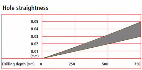
Hole straightness
Surface quality
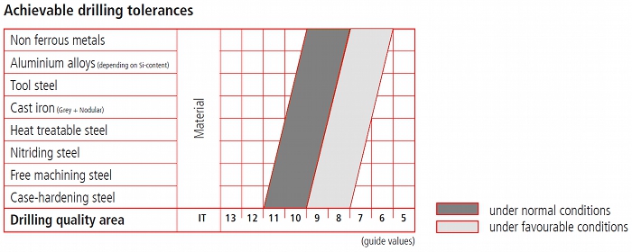
Drilling tolerances
In the following illustration the drilling process with single flute drills is shown.
The cooling lubricant supply, chip removal and the W-shaped drill-hole (created by the eccentrical cutting edge) reveal the differences
to conventional twist drilling. 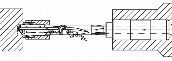
Deep-hole bores starting at Ø 18 up to 100 mm - drilling with BTA (Single Tube System / STS)
|
Runout (drift of the tool): |
0.1 mm / 100 mm drill depth within a total drilling depth of 70 x bore diameter |
|
Bore diameter tolerance: |
0 / +0.1 mm up to bore diameter 100 mm equals IT8 (depending on the material) |
When drilling with BTA-System a drill head with replaceable cutting inserts is used.
The drill head is screwed on a tube depending on the desired drilling depth.
The cooling lubricant is supplied between the tube shell and the drill-hole itself.
The chips are removed internally through the tool.
|
|
Basic information for premachining
For the drilling process the pre-centering or pilot-bores are not needed,
besides that threads should be manufactured after the deep-hole drilling process to prevent them from being damaged by the gun drill.
Listed below you will get a recommendation how the workpieces should be premachined. Excepting the described premachining there should not be any other.
An illustration of the corresponding premachining is shown on the following links.

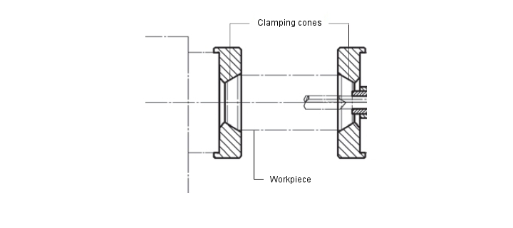
cylindrical shaped workpiece with concentrical bore
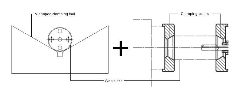
Cylindrical shaped workpieces with concentrical bore are being clamped in cones and should therefore be chamfered on both sides.
To guide the gundrill a drill bush (not shown) is pressed against the workpiece, therefore the workpiece should be faced on both sides.
cylindrical shaped workpiece with exccentrical bores
The workpieces are being fixed on V-shaped clamping tools and should therefore be outside-turned. As well the fronts should be faced to have the drill bushing pressed on properly.
Illustration: Premachining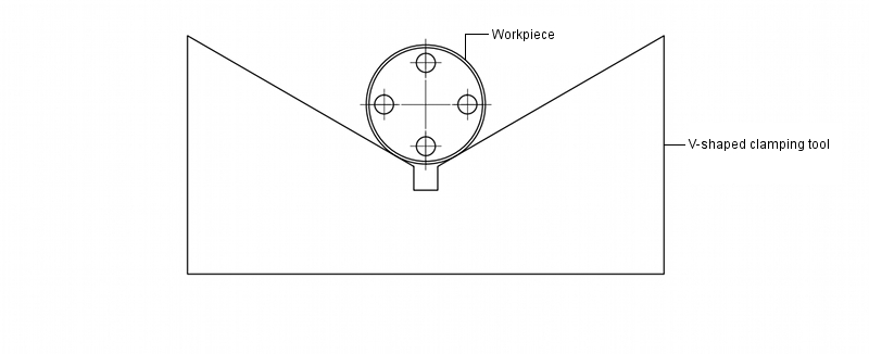
cylindrical shaped workpiece with concentric and exccentrical bores

Plates and block-shaped workpieces
To have the drill bushing pressed on properly (illustration) the plates and block-shaped workpieces should be milled perpendicularly on every side.
Illustration: Premachining
|
|
© Graf + Klett GmbH 2026 |
|